In this third instalment of my Tronxy Klipper conversion, I’m going to cover how I went about hooking everything up to the Octopus Pro motherboard using the extended wiring looms I created in part 2. If you haven’t been following my Klipper shenanigans here are the links to the previous posts:
- Tronxy x5SA-600 Klipper Conversion Part 1 – The Exciting Bit – Buying Parts
- Tronxy X5SA-600 Klipper Conversion Part 2 – The Scary Bit – Rewiring
The Octopus Pro is a relatively high end 3D printer motherboard. Some of its features include:
- Cortex M4 32 bit processor (I went for the F429 version which gives up a little clock speed for 1Mb flash memory which is needed for RepRap firmware if I ever decide to go that way)
- 8 Support for up to 8 motors
- USBC port
- 8 Fan controllers
- Fused circuits to protect the board against short circuits


Driver Operation Mode Configuration
The first step was to configure the stepper motor operational mode to UART. This is done by removing / adding jumpers. Why UART mode? I think it’s one of those things that’s obvious to everyone, but no one actually explains the difference. I certainly couldn’t find a concise answer when I Googled it. In simple terms I think UART mode means is software configurable and allows 2 way communication between the hardware and software, while step/standalone mode required soldering or moving jumpers around to change settings. On top of this, the Klipper configuration guide states this:
Klipper can also use Trinamic drivers in their “standalone mode”. However, when the drivers are in this mode, no special Klipper configuration is needed and the advanced Klipper features discussed in this document are not available.
https://www.klipper3d.org/TMC_Drivers.html
So, really it was a no-brainer to use UART mode after reading that.
So, here are the jumper settings used to put the drivers into UART mode on the motherboard:

By default the Octopus Pro motherboard has 4 jumpers in place for each motor, so I had to remove 24 of them.
Installing The Drivers
The drivers shipped from Biqu, came in a box of 4, with the heatsinks not yet attached. Attaching the heatsinks was simply a matter of removing the backing off the double sided tape on the bottom of the heat sink and then gently placing it on the driver board over the gold coloured pad. A little bit of pressure to make sure it’s stuck down may have helped.

The driver also came with a little jumper cable, but I don’t know what it’s for. I assume it’s for use in standalone mode, but I never used it with the driver. Having 8 of them did come in handy when I was connecting my Raspberry Pi to the Octopus Pro board, but more about that later.
The next step was to install the drivers into the board. I needed 5 installed as follows:
| Driver Port | Motor |
|---|---|
| Motor0 | X Motor |
| Motor1 | Y Motor |
| Motor2 | Z1 Motor |
| Motor3 | Z2 Motor |
| Motor4 | Extruder Motor |

You might notice I have 6 drivers installed on the above pic. The 6th one was for testing when I was having trouble getting the extruder to work. The problem turned out to be a software config error, that I’ll describe in part 4.
I’m not sure if all TMC drivers are like this, but the BTT ones were colour-coded with the BTT Octopus Pro motherboard. So when inserting them into the board I made sure that I aligned the red pins with the red part of the socket. Care needs to be taken here as it’s quite easy to misalign the pins.
Sensorless Homing Stallguard
In some 3D printers they use sensorless homing by effectively crashing into the end of the frame. This causes a change in current and the motherboard can then send the signal to stop the motor. Since the Tronxy uses end-stops, I’m not using Stallguard and the Stallguard jumpers for the drivers need to be removed from the motherboard. I initially didn’t remove these jumpers and found that my end-stops were being ignored.
The following image shows their location:

Connecting The Motors
With the drivers installed, it was now easy to install the plugs for the stepper motors. They were plugged ins as follows:
| Socket | Stepper Motor |
|---|---|
| Motor0 | X – Axis |
| Motor1 | Y – Axis |
| Motor2_1 | Z1 – Axis |
| Motor2_2 | Unused! |
| Motor3 | Z2 – Axis |
| Motor4 | Extruder Motor |
Notice how Motor2 has 2 sockets? This isn’t 2 independent sockets, but rather a split of motor 2 that use the same driver. What this means is that if you have 2 motors plugged into these 2 sockets, the 2 motors will move in time with one another. It sounds like what I want with the Z motors but it’s not. Sometimes (more like anytime) when the Tronxy is idle, the stepper motors lose their current and the weight of the bed with gravity means the bed falls down to 0.
In theory both sides should move in sync, but there’s no guarantee of that. So I need the 2 motors to work semi-independently of one another. This means using 2 drivers and motor ports. The Klipper firmware will take care of keeping them in sync. If the 2 motors were connected with a belt which is a common ”upgrade” on these Tronxy printers, it may be feasible to use Motor2_1 and Motor2_2 as they would then be guaranteed to be in sync.
End Stops
With the drivers and motors set up, my next area of focus was the end-stops. This was much simpler than setting up the motors as there were no jumpers to set. It was just a matter of plugging in my wires to the board. There are 8 end-stops on the Octopus board that can align to the 8 motors. In theory you can you and motor with any end-stop, but to keep things simple, I made sure that I matched the end-stop number with the motor number:
| Octopus End-Stop | Physical End-Stop |
|---|---|
| Stop0 | X-Axis end-stop |
| Stop1 | Y-Axis end-stop |
| Stop2 | Z1-Axis end-stop |
| Stop3 | Z2-Axis end-stop |
| Stop4 | Extruder end-stop |
BLTouch
For the BLTouch, I purchased a BLTouch from Creality. Creality sells a genuine Antclabs BLTouch, but it comes with different coloured wiring to the standard BLTouch. Creality has swapped the brown wire with a blue wire. Other than this, everything is exactly the same. The Octopus Pro has a BLTouch socket built into the mother board. So it was simply a matter of connecting the extension wires I described in Part 2 to the BLTouch socket on the motherboard.

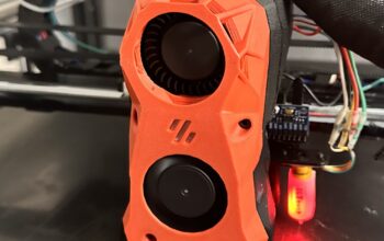
Fans
Fans came next. Much simpler than everything else so far. There’s only 2 fans in this system so far – a hot-end fan and a part cooling fan:
| Octopus Fan Port | Physical Fan |
|---|---|
| Fan0 | Hot-end fan |
| Fan1 | Part cooling fan |
The fans also need to run in 24V mode. This is configured by setting the fan voltage jumpers:

Each fan can be set individually for 5, 12 or 24V. I set them all to 24V as I intend to keep things 24V across the board. This reduces the risk of plugging in a fan of the wrong voltage and blowing something.
Hot-End and Heat-Bed Wiring
The hot-end wiring was likewise relatively simple and went into the HE0 socket, however the wiring for the heated bed required a bit more work.
| Octopus Heater Port | Physical Heater Device |
|---|---|
| HE0 | Hot-end heater cartridge |
| HE1 | MOSFET board for heat bed |
This is where it start to get tricky. As powerful as the Octopus Pro board is, it just doesn’t have the capacity to power a bed a big as the 600x600mm on the Tronxy X5SA-600. To adequately supply power to this, I needed to add a MOSFET board and run an extra set of power cables from the existing power supply. The main power supply therefore runs 2 sets of outputs. One goes from to the input of the Octopus Pro, the other goes to the input of the MOSFET board. HE1 from the Octopus Pro goes to the Bed input on the MOSFET and the Hotbed output on the MOSFET goes to the bed. Confused? Here’s a diagram that shows how it’s all connected:

You might want to zoom in on that one and read some of the detail. Note that on the output side, the polarity of the wiring to the heat-bed does not matter. This is why the Tronxy and I assume others have 2 read cables for the heat-bed wiring. I’ve decided to run all power for this machine from a single power supply, however it is entirely possible to use seperate power supplies for this purpose. The Octopus Pro even has another power input to allow a seperate power supply for the motors. Remember, this is an off-the-shelf motherboard, so it’s use is not limited to 3D printers like the Tronxy. There’s potential for other styles of 3D printers to be used with this board. Those giant 3D printers they use to build houses need a motherboard too. Could this be scaled up to that? I think it could!
Thermistors
Now that the heaters are hooked up, it’s time for the thermistors. These were very simple as the extended wires just plugged straight into the Octopus Pro thermistor ports. No jumpers or other fiddly bits to deal with.

Connecting The Raspberry Pi
When it came time to connecting the Raspberry Pi, I made the decision to use the SPI pin headers of the Raspberry Pi and leave the USB ports free. The main reason for this was that I planned to create a custom enclosure for the electronics with most of the expansion ports accessible from the outside and I didn’t want a USB cable coming out and then going back into the enclosure.
This is where the little Dupont cables that came with my Stepper drivers came in useful. Since I didn’t need them for the stepper drivers, they were the perfect size for this purpose. One small caveat is that these wires are extremely thin. I have been getting undervoltage warnings on my Raspberry Pi and reading up about this online, it seems that using undersized wire for the 5V connections could cause this. Upgrading these wires is on my TODO list.
I found the user manual that came with the Octopus Pro to be lacking somewhat in detail when it came to how to actually making this connection. My last resort was to post online in a Facebook group to get the answer and this is what it looks like:

IMPORTANT: If you are connecting using the SPI interface as I am here you need to make sure that there’s no USBC or other power connections made to the Raspberry Pi. This will almost surely blow the circuits on the Raspberry Pi and could extend to taking out the Octopus Pro and other connected devices with it.
| Octopus Pro J26 UART2 Pin Name | Raspbery Pi Pin Number | Raspberry Pi Pin Name |
|---|---|---|
| 5V | 2 | 5V |
| 5V | 4 | 5V |
| Ground | 6 | Ground |
| RX | 8 | UART TX |
| TX | 10 | UART RX |
Of course, no facebook user group comment section is complete without someone becoming abusive! There was an exchange of words between a couple of users about why you would want to do it this way since USB is so much faster, which was quickly shut down with “you’re an idiot” type comments about how it’s not slower. In the end I’m not sure if it is or not, but everyone at least seemed to agree it’s adequate for the purposes of 3D printing.
BOOT0 Jumper
Removing the BOOT0 jumper from the Octopus Pro motherboard allows it load new firmware from the SD card. It took me a few days to figure out that was the reason my Klipper firmware was not being installed.

The BOOT0 jumper is located just under the bottom left corner of the MOTOR7 driver socket.
Connecting The BTT TFT70 LCD
I found this part a bit disappointing. I went out and bought a nice big LCD Touch screen to use with Klipper and the Octopus Pro only to find that Klipper is not compatible with any touch screen. Klipper only works with emulated 12864 mode. Which basically means a 128 x 64 pixel LCD screen with a button / dial to control it. I hooked it up anyway, because it is useful, but had I realised this I probably would have just gone for a TFT35 and saved some hard earned cash. I looked into using this with the Raspberry Pi, but it’s unfortunately not compatible. There is a Raspberry Pi specific version that needs to be purchased.
The TFT 70 comes shipped with 3 ribbon cables, 1 of them is for use as a touch screen and the others are for the 12864 emulated mode. I hooked up all three of these thinking I’d be able to switch between them 🙁


This wiring was straight forward. EXP1 to EXP1, EXP2 to EXP2 and RS232 to TFT on the Octopus Pro.
| TFT70 Pin Header | Octopus Pro Pin Header | Octopus Pro Pinout Number |
|---|---|---|
| EXP1 | EXP1 | J39 |
| EXP2 | EXP2 | J43 |
| RS232 | TFT | J70 |
Adding an Accelerometer
The final piece of wiring was to add an accelerometer. The accelerometer is used to measure resonances created by the 3D printer when making fast movements. It then counters these resonances in the stepper motor movements to reduce ringing or ghosting in prints. The wiring is as follows:

Note that the accelerometer is wired to the Raspberry Pi and not to the Octopus Pro motherboard. Klipper takes care of this processing on the Raspberry Pi.
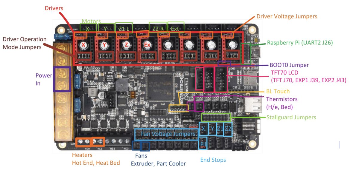
Octopus Pro Wiring
And that’s all the wiring done! Here’s a diagram I created that shows exactly where I plugged everything into the Octopus Pro board.