In part 1 of my Klipper conversion, I detailed all of the parts I purchased to make this happen. Now that I had all the parts, it was time to start putting it all together and job 1 was modifying the wiring loom. The original Tronxy motherboard used a 30pin ribbon cable that led to a breakout board on the X-axis gantry. My original plan was to re-use this 30 pin ribbon cable and I ordered a couple of IDC30 breakout boards to allow this.
While I was waiting for these to arrive (3 weeks from China), I had a 3D printing mishap that ended with a big blob of filament stuck to the bottom of my hot end and into the hot end cooling fan. I found out a couple of days later that this also took out my Tronxy bed levelling sensor.
I ordered a new Tronxy bed levelling sensor online from eBay, but no surprises here, it was going to be 3-4 weeks for it to be delivered from China. So I started to look into other bed levelling sensors and there were many favourable stories about the BL Touch sensor from Antclabs. A big plus was that I could get one shipped overnight from Amazon and that would get me going quick enough. Only problem was that the BLTouch uses different wiring than the Tronxy sensor. The Tronxy sensor uses a 3 wire connector as opposed to the BLTouch 5 wire connector. The additional 2 wires are used to provide power to deploy the probe that the BLTouch uses for measurement. So it was at this point I decided I would do away with the 30 pin ribbon and run a new wiring loom to my new board.
Removing the 30 pin ribbon cable
Removing the 30 pin ribbon cable was easy enough. There’s a couple of screws at the end of the X-axis gantry holding in the cover the the breakout board was connected to. I undid the screws and then another couple of screws to remove the 30 pin breakout board. The ribbon cable itself was easy to remove and unplugging the wires from the breakout board was straight forward. Fortunately, Tronxy had clear labels on the wiring harness so there was no chance of mixing things up later when it was time to connect everything up again. Easy!


The next challenge was extending the existing wires from the gantry down to the new motherboard. I made a decision early on that I wanted the motherboard and new display to not be tethered to the top of the printer like it was on the original. This was especially important during testing and setup as the motherboard was living under the printer. I took a very rough measurement and decided that I needed about 2.25m of additional length for each wire. Actually I didn’t measure and just took a piece of wire and cut it where I thought it was long enough. All other wires were measured against that first one.
Although there was a 30 pin ribbon cable running through in the original setup, only 22 of those wires were being used. In addition to this I needed 2 more for the BLTouch and 6 more for the accelerometer, meaning a total of 28 wires need to be extended.
Extending the existing wiring loom
The original wiring loom of the Tronxy was using standard JST PH2 connectors where it plugged into the 30 pin breakout board and also into the motherboard. So I bought a kit with a bunch of assorted connectors and a crimping tool. I already had a wire stripping tool.
In the start crimping the wires proved extremely challenging. This was because the crimping tool I bought wasn’t suitable for the JST connectors despite being told at the store that it was. So I ordered a replacement tool and while the results were better, it was still a challenge.
The issue I had was that whenever I would crimp the connectors to the wire using the tool, I would more often than not manage to cut the tip off the wire. At first I thought that this was because I had poor quality wire. Then purely by chance I realised I was doing it wrong.
The die in the crimping tool has a large side and a small side, the difference is not easily noticeable until you look closely. The correct way to do it is to make sure the plastic shielding on the wire is aligned with the larger side of the die. To make it a little easier my process was as follows:
- Strip the end of the wire using the wire strippers – around 3mm
- Place stripped end of the wire in the connector
- Using a pair of pliers, gently squeeze in the tips of the connector until it’s just tight enough to grip the wire. We’re not trying to crimp it in this step but just making it temporarily hold
- Place the wire with the connector into the crimping tool with the wire shielded side in the larger side of the die and give it a good squeeze
The result is a perfectly crimped wire every time.


Just when I thought my problems were over, I had to deal with another wiring problem. The JST connector set that I purchased had a female side that is crimped as described above, but the male end is designed to be soldered into a PCB. Alternatively, it can be soldered to the end of my wiring loom, but the whole reason I bought this kit was to avoid soldering.
My soldering skills are rubbish, but did improve over time. The biggest problem is my soldering iron is a cheapo that has a relatively short duty cycle, so it only stays hot for a few seconds before it cools off and I have to wait for it to reheat again. The other issue was holding the wires in place while trying to solder them. I was effectively trying to do it in the air so it was really difficult to get a good result.
What did work for me eventually was as follows:
- Place a piece of heat shrink insulation over the wire. a 15mm piece is plenty and position in 5-10 cm past the tip of the wire
- Strip the end of the wire using wire strippers – around 5mm
- Apply a small amount of solder to the end of the wire on it’s own
- Hold down the JST plug using any means possible. I found placing a hammer on top of it held it in place quite well
- Position the tinned wire over the tip of the JST plug and use the soldering iron to melt the tinned wire over the plug
- Hold the wire in place for 2-3 seconds after the heat was removed to let the solder harden and leave the wire in place
- Once the wire is in place move the heat shrink insulation over the soldered joint and shrink it using a cigarette lighter. Aim to get the tip of the flame just below the heat shrink but don’t leave it too long or you will burn it
And so after 28 of those, I was ready to start hooking it all up! It was just a matter of plugging the JST headers to the existing wires and run the new cables down the side of the printer, ready to be plugged into the motherboard.
Tronxy QA fail
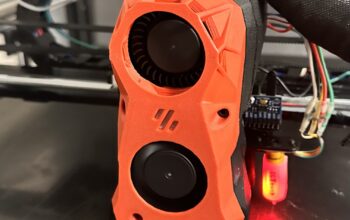
One of the things that has bothered my since getting this printer is that I’ve never noticed the part cooling fans ever working. I’ve never really looked into the root cause, but it’s something I’ve always been aware of and wanted to make sure I sorted as a part of this upgrade.
While extending the existing wiring loom, I finally managed to find the root cause. The two cooling fans were joined together in parallel, but they inexplicably had their polarity reversed when connecting to the JST connector. They had joined the to red wires from the two fans to a black wire in the plug, and vice versa for the black wires. I can’t understand how or why this was done!
A final note about the Tronxy 30 pin breakout board
I hadn’t looked to closely at the breakout board before writing this. One pair of the wires that needs to run through the 30 pin ribbon cable is the power to the hot end. Hot end wires are usually quite thick to handle the current flowing through them. Surely the tiny diameter wires running through a ribbon cable wouldn’t suffice without overheating or burning, but somehow it seems adequate.
Well when I went to have a closer look to take photos, what I noticed was that the hot end isn’t using a single wire through the ribbon for the positive terminal. It’s actually using 4. I don’t know enough about electronics to say whether or not this is a sound engineering design, but it does appear to work.

Extending the BLTouch Wires
The BLTouch extension wires were a little different to the other wires I extended. BLTouch has a micro sized connector on the side of the probe and Dupont style connectors on the other end. The correct thing would have been to buy some Dupont connectors for my wire extensions and run those to the motherboard, but I couldn’t easily source them locally and wanted to get this thing done! So I made the decision to cut the Creality BLTouch wiring harness in 2 and attach JST clips in the middle that I could then connect to my extension wires. Same outcome, different execution.