I’ve had the Tronxy for over 6 months now and the results have been mixed. Some of it has been due to the steep learning curve that comes from having a new toy and some of it has been because of the limitations of the device. While Marlin is a great firmware and one of the main reasons I chose this model over many the others, the Marlin firmware installed by default seems to be somewhat locked down / missing features.
An example of this is Tronxy has locked down the board by removing the bootloader. This means that the only way to update the firmware is to get it from Tronxy direct. So if new features come out in Marlin, you’re at the mercy of Tronxy to get this update. Also, the UI is quite limited. I’ve seen online other people have referred to live Z tuning – meaning if your Z Offset is slightly off, you can make an adjustment while it’s printing and hopefully save the piece you’re printing.
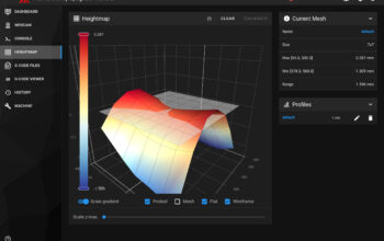
With the firmware being locked down in this way it also prevented me from adding items to the config like skew compensation. This refers to the ability of the firmware to compensate for an unsquare printer setup – my Tronxy is out by around 1 degree from square, so I can’t print a perfect circle. Also it means I can’t print dimensionally accurate parts.
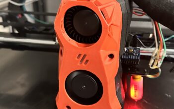
Another reason I really want to upgrade to Klipper, is resonance compensation. Resonance compensation uses an accelerometer to measure the vibration the the printer produces while printing. It then sends signals to the stepper motors to cancel this out, effectively eliminating ghosting / ringing in prints.

So with all of this in mind I went out and put together a shopping list:
- 1 x BTT Octopus Pro motherboard
- 8 x TMC2209 Stepper Motor Drivers (Although I only need 5)
- 1 x BTT TFT70 LCD screen (In retrospect a TFT35 would have been more than sufficient)
- 1 x BTT PI TFT70 LCD screen (I haven’t got this yet, but it would be nice to have)
- 1 x Raspberry Pi 4
- 1 x MOSFET board
- 2 x IDC30 breakout board (optional if you want to keep the ribbon cable. Only 1 is needed if you don’t plan on changing to BLTOUCH or adding an accelerometer)
- 1 x BLTOUCH bed levelling sensor (TR Sensor is fine to keep, but mine got damaged and a BLTOUCH was easier to acquire locally)
There is a global shortage of Raspberry PI 4 boards currently. So it can be difficult to come by. I’ve heard that there are other boards that can be used, but I haven’t tried them.
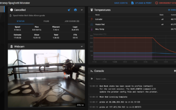
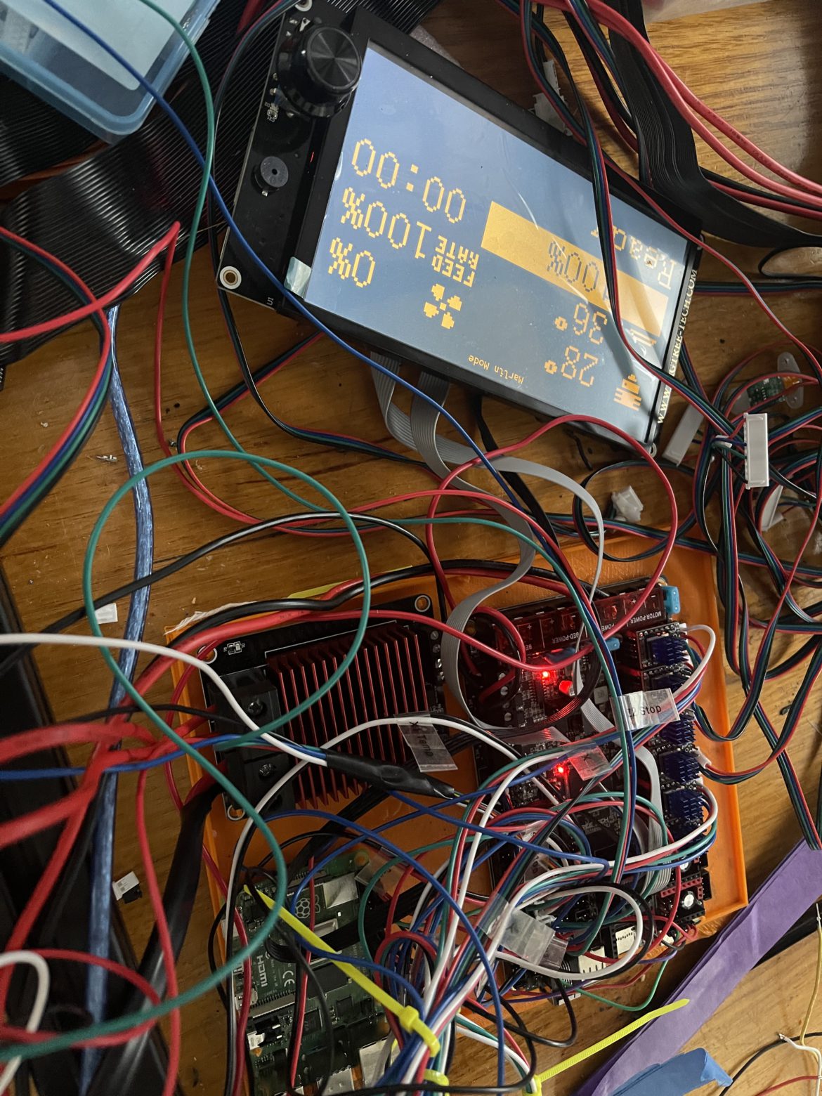
Here’s what all that looks like when it’s together and working. There’s still more work to do to clean up the wiring and build an enclosure for the electronics.